Sensors and instruments: the key points
Ultrasound contact sensors are resonant sensors. Their sensitivity is an important point, but not the only one. The basis of Condition Monitoring is to trend data and to perform a corrective action when an alarm is triggered. If you have no guarantee that two sensors provide a similar result for the same signal, then change supplier. Your historical data and alarm thresholds will become useless when replacing a defective sensor!
Therefore, as for all technologies, the transducer characteristics: the sensitivity and the resonant frequency; must be clearly specified and certified by the manufacturer. In fact, SDT is in a position to provide such guarantees because we are able to offer customers sensors with standardized measurement reception quality.

Specifications of SDT RS2T Threaded sensor
The same remark is valid for the measurement device. The instruments must be calibrated and interchangeable without inducing measurement variation. Ideally, the input, receiving the sensor signal, has to be under control, not necessarily the heterodyne audio output.
Listening is the primary defense line.
The first functionality of an ultrasound device is to transform high frequency to audible sound. The operation is called heterodyning. People not familiar with ultrasound instruments think this is an old-fashioned and outdated method. In fact, it is not, and this is especially the case when inspecting low-speed machinery. An operator without deep knowledge can distinguish a healthy bearing, producing a quiet steady signal from a defective bearing, causing an intermittent or specific repetitive ringing or crackling sound.
However, listening is not enough. Reliable measurements are required to build a solid PdM program. Otherwise, your instrument is no more than a stethoscope.
Static measurements for failure detection
Static measurements (overall values) are simple to implement as the result is just numbers. They are easy to manage for storing, trending curves and triggering alarms. For low-speed bearings, two indicators provided by static measurements are used: the RMS, which characterizes the signal energy and the Peak, which characterizes the signal amplitude. Combining these 2 indicators, early failure detection is easy to find.
Example of Static data results
Here is the data comparison coming from machinery running at 50 rpm, using an acquisition time of 20 seconds:

Dynamic measurement: from detection to diagnosis
In some cases, for example a complicated machine or repetitive unexpected failures, the user wishes to go beyond the detection process objective of determining the presence of a fault. The need is to determine which component is defective. This is the diagnosis process performed using Dynamic measurements.
A Dynamic measurement is data acquisition over a selected duration. It is used to process time domain and frequency domain (FFT or spectrum) representations. For ultrasound technology, time domain representation is the preferred tool because the time signal works with intermittent signals and provides powerful information on the nature of the failure and the failure severity.
First, the shape of the time signal indicates the failure presence with the visual interpretation of the time signal, showing, for example, repetitive impacts. The time signal can be analyzed in an identical way to vibration analysis to provide an indication of the cause of failure. Like vibration, the rotation speed of the machine and a detailed machinery schematic are required. In the case of a later stage defect in a bearing, the operator can measure the duration between impacts. Comparison with defect calculations derived from schematics can help identify the failed bearing and, therefore, the bearing failure origin, the root cause. Finally, the impact amplitudes are often a good indicator of the failure severity.
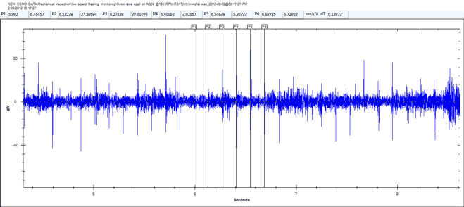
The duration between adjacent impacts provides the bearing defect frequency.
Example of Dynamic data results
Here is the time domain comparison coming from machinery running at 25 rpm, using an acquisition time of 5 seconds.
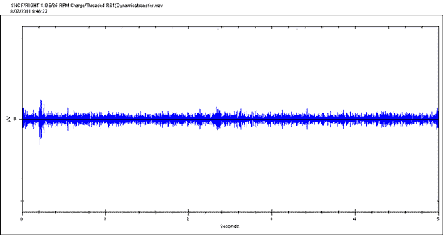
Time signal for a healthy bearing
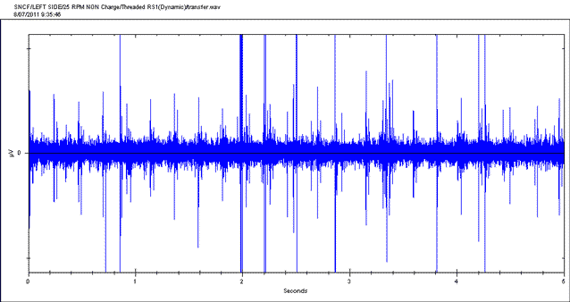
Time signal for a defective bearing
Note: the same vertical scale has been used for the two time signals above.
The duration between impacts corresponds to the Ball Pass Frequency Outer race (BPFO). The diagnosis is that the bearing will have some damage on the outer race.

The duration indicates the bearing defect frequency.
The diagnosis is outer race damage on this bearing.
The Bearing Toolbox
To make life even easier for maintenance technicians when establishing these diagnosis, SDT has developed a Bearing Toolbox in the UAS3 software. No more time-consuming calculations and endless searching through bearing manufacturers’ manuals to find the necessary data. With this feature, one can simply select a bearing from the database (more than 50K references), then enter the machine running speed to identify whether or not an acquired signal (vibration, ultrasound) matches with one of the four known bearing fault frequencies.
Watch this informative video to get a better perspective of how time saving it can be!
Conclusion
Definitively, ultrasound is an excellent method for dealing with low RPM machinery.
The advantages offered by the technology are clear: efficiency , simplicity, the possibility to combine an easy detection with a more elaborate diagnosis and time saving thanks to the Bearing Toolbox.
We keep in mind the pertinent remark made by a Maintenance Manager: “My department does not have the budget to cover the expenses of a team of 5 vibration experts. In addition, with 5 guys, we would monitor only the critical machines. With our ultrasound instruments, the first line is operated by basic technicians, even the lubrication technicians, and most machines are regularly inspected. 80% of the problems found are solved using ultrasound. My single vibration expert is used to solve the remaining 20%.”
LUBExpert in Dynamic mode can help situations like this one. In fact, the lubrication technician can take measurements while lubricating, so the Condition Monitoring (CM) team doesn’t have to check those machines again.
SDT has a solution, it’s called Ultrasound.