Vigilant
A turn-key condition monitoring solution combining the versatility of ultrasound, the analytics of vibration, standard communication protocols and an embedded trending and analysis software.
Configure Vigilant to any Critical Asset
Vigilant is a flexible data collection pod. Input any combo of eight ultrasound and vibration sensors and receive continuous feedback from your assets.
4 channels for Temperature, Tach and Pressure create an all-in-one solution for critical and guarded assets.
Vigilant Highlights:
- 8 channels (Ultrasound or Vibration)
- 4 channels (Temp/Tach/Process)
- Embedded data management software
- Trends/Spectrum/Waveform/Waterfall
- Open communications protocol
- Static and Dynamic data
Designed for CONMONSense
Vigilant accepts data from commonly available sensors including the CONMONSense Sensors from SDT, designed to provide repeatability in any industrial environment.


Embedded Data Management Software
View the status of any asset from the security and convenience of your favorite web browser.

 Configuration
Vigilant includes a web interface to configure all the system options and monitoring features available on the units.
 Alarm Log
From any of the desktops the users have access to the “Alarm Log” that shows all the events or anomalies detected in the monitored machine in real-time.
 Widgets
Widgets for static trends, dynamic time waveform plots, as well as spectral analysis.
 Layouts
Size, position, and arrange widgets to create custom desktop layouts.
 Dashboard
The Dashboard visualizes the real time measurements performed by the Vigilant. It also shows the historical data stored in the unit.
Applications
- Early detection of rolling element bearing faults (especially in slow speed applications);
- Status of couplings on critical assets in limited access locations;
- Monitor guarded assets such as robotics or CNC machine centres;
- Lubrication status of roller bearings;
- Valves deemed critical to a process;
- Detection of partial discharge in electrical assets such as MCC panels and switchgear cabinets;
- Detection of friction or impacting in linear motion applications;
- Detection of turbulence produced by cavitation in pumps and valves;
- Detection of hydro-cyclones used in mining processes.


Vigilant Permanent

- 8 high-speed (Dynamic) multipurpose analog inputs;
- 4 channels (Temp/Tach/Process);
- ICP power source available on all dynamic inputs;
- Ethernet TCP/IP communications;
- Powered at +24 Vdc.
Vigilant Mobility

- Same function as Vigilant Permanent;
- Packaged in rugged, custom waterproof case;
- Designed to travel to off-site assets;
- Install on assets in alarm to closely monitor until planned shutdown.
CONMONSense RSV (0-10V Sensor) FAQ
Note that the sensor does need an external 24VDC supply capable to deliver at least 40 mA.
CONMONSense wiring:
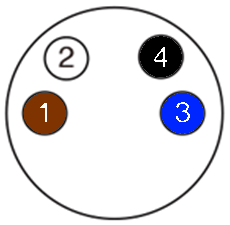
1 = 24VDC Power supply (+)
2 = Voltage output (Vout)
3 = 0V (-)
4 = Communication line (should be left floating if not used)
If your system has a dedicated 0-10V analog voltage input, here is a possible wiring:
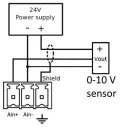
Note that this wiring is only used as an example, you should refer to your system technical document to ensure a correct wiring with your installation.
Static mode:
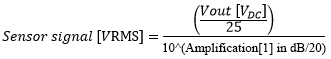
Equation for each amplification:
![]()
Example: an output voltage of 5 [V] will result in a sensor output voltage of (5 / 25) = 0.2 [V] or 200 [mV] or 106 [dB]µV
![]()
Example: an output voltage of 5 [V] will result in a sensor output voltage of (5 / 100) = 0.05 [V] or 50 [mV] or 94 [dB]µV
![]()
Example: an output voltage of 5 [V] will result in a sensor output voltage of (5 / 400) = 0.0125 [V] or 12.5 [mV] or 82 [dB]µV
![]()
Example: an output voltage of 5 [V] will result in a sensor output voltage of (5 / 1575) = 0.0032 [V] or 3.2 [mV] or 70 [dB]µV
![]()
Example: an output voltage of 5 [V] will result in a sensor output voltage of (5 / 6275) = 0.0008 [V] or 0.8 [mV] or 58 [dB]µV
![]()
Example: an output voltage of 5 [V] will result in a sensor output voltage of (5 / 25000) = 0.0002 [V] or 0.2 [mV] or 46 [dB]µV
Dynamic mode:
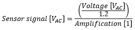
Equation for each amplification:
![]()
Example: a dynamic output voltage of 1 [V] will result in a sensor output voltage of (1 / 1.2) = 0.833 [V] or 833 [mV] or 118.3 [dB]µV
![]()
Example: a dynamic output voltage of 1 [V] will result in a sensor output voltage of (1 / 4.8) = 0.208 [V] or 208 [mV] or 106.3 [dB]µV
![]()
Example: a dynamic output voltage of 1 [V] will result in a sensor output voltage of (1 / 19.2) = 0.0521 [V] or 52.1 [mV] or 94.3 [dB]µV
![]()
Example: a dynamic output voltage of 1 [V] will result in a sensor output voltage of (1 / 75.6) = 0.0132 [V] or 13.2 [mV] or 82.3 [dB]µV
![]()
Example: an output voltage of 1 [V] will result in a sensor output voltage of (1 / 301.2) = 0.0033 [V] or 3.3 [mV] or 70.3 [dB]µV
![]()
Example: an output voltage of 1 [V] will result in a sensor output voltage of (1 / 1200) = 0.00083 [V] or 0.83 [mV] or 58.3 [dB]µV
Note that the dynamic mode is an alternative output (AC) with a bias voltage (DC) of 3 [V]. A dynamic output of 1 V means 3 V DC + 1 V AC
In order to modify the internal amplification of the sensors or to switch from static to dynamic mode, a communication needs to be established between the PLC and the sensor.
Using a digital output
If your PLC has a digital output module you can connect one output to the sensor communication line using this kind of schematic:
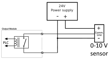
Then simply generate pulses according to the CONMONSense datasheet in order to modify the amplification or the mode.
Using a serial communication
It is also possible to communicate using a serial communication with the following specification:
• Protocol: UART
• Baudrate: 9600 bps
• Data bits: 8
• Parity: Even
• Stop bit: 1
CONMONSense sensors are using a proprietary protocol described in the datasheet.
The best way to implement an amplification control is by following these simple rules:
Static mode
- If the output voltage (DC) is higher than 5 [V] decrease the amplification by one step (12 [dB])
- If the output voltage (DC) is lower than 1 [V] increase the amplification by one step (12 [dB])
Dynamic mode
- If the signal peak is higher than 4.5 [V] (or 1.5 [V] if bias voltage is removed) decrease the amplification by one step (12 [dB])
- If the signal peak is lower than 3.5 [V] (or 0.5 [V] if bias voltage is removed) increase the amplification by one step (12 [dB])
Note that the dynamic mode is an alternative output (AC) with a bias voltage (DC) of 3 [V].