CONMONSense Range
CONMONSense Range is a Standalone, Permanent Mount, Ultrasound Sensor designed to integrate with standard industrial measurement systems
CONMONSense delivers precise, repeatable data about the health of your assets and electrical systems also in the most challenging environment.
Its resonant piezo element is optimized for ultrasound driven lubrication, mechanical fault detection, and monitoring the health of valves, steam, hydraulic systems and electrical defects.
Ultrasound is a true measure of the FITness of your facility. Most assets produce FRICTION, IMPACTING, and TURBULENCE as defect indicators. CONMONSense hears these phenomena at their inception and delivers an analog signal response to your connected measurement system.
With an output range from 4-20 mA (static and/or dynamic) or from 0-10 V, CONMONSense mounts permanently to any asset to provide continuous condition monitoring data.
Avoid unplanned downtime and put the safety of your plant and colleagues first.
CONMONSense Contact Sensor
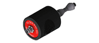 Permanent contact/structure (IP65) sensor for continuous monitoring bearings lubrication, valves, steam traps, hydraulics systems and rotating assets, even the slowest ones.
CONMONSense Airborne Sensor
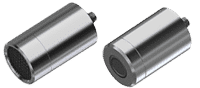 Airborne open (IP40) and enclosed (IP65) for inspection of electrical systems.
The design of this sensor allows precise and repetitive measurements to continuously monitor your electrical cabinet’s health. Put the safety of your plant and colleagues first.
Questions concerning CONMONSense Range
CONMONSense Range
The CONMONSense range employs an embedded electronics system that performs the heterodyne process within the sensor itself. Unlike the SDT sensors of the SDT handheld devices, the SDT CONMONSense sensors directly provide audible signals that can be acquired and stored by your existing systems. This eliminates the need for dedicated SDT handheld devices requiring higher sampling rates, making the monitoring process more efficient and easier to implement in your organization.
While the CONMONSense sensors offer advanced compatibility, their electronics result in a minimum measurement capacity close to 15-20 dB[μV] (depending on the mode) which means that, in this case, sensors dedicated to the SDT handheld instruments should be preferred. This means that CONMONSense may have limitations when it comes to measuring weak signals. In summary, the typical background noise, and the capability to acquire weak signals remains typically x 2.5 times better for the combination of the SDT instruments sensors compared to CONMONSense connected to a third-party acquisition equipment.
In compliance with ISO 29821:2018, 2 designs are available, namely:
- structure borne or contact resonant sensor.
- airborne sensors, having different IP ratings (IP65 and IP40) to best suit the constraints of your environment.
| Ultrasound pillar | Leaks |
|||||||
| Main ultrasound source/ CONMONSense recommendation | Structure borne | Structure borne | Airborne | Airborne | Structure borne | Structure borne | Both | Airborne + liquid Not covered by CONMONSense |
| Dedicated SDT solutions | RS2T RS2NL100-300-500 | LUBESense1 | Flex ID2 AIRSense ULTRASense | Flex ID2 AIRSense RS2A ParaDish2 | RS2T RS2NL100-300-500 | RS2T RS2NL100-300-500 | RS2T RS2NL100-300-500 | TTS2 |
Here are the four popular types of analog outputs commonly use in industrial settings:
- 4-20 mA
- CONMONSense, version RSC.00X, delivers a 4-20 mA analog current output, in dynamic mode (AC mode). This output standard is widely used in process control instruments, due to its reliability and ease of integration. The cabling requirements vary depending on the configuration. The CONMONSense RSC supports “active loop” and “passive loop”. In “loop powered/passive loop configuration”, the current loop is utilized as the power supply, which means that only 2 wires are required. On the other hand, in “passive configuration “, one additional connection is necessary to provide power to the sensor (+24 V DC). In both cases, the most appropriate Gain, corresponding to an optimal range of [4-20 mA] is to be configured by the user.
- CONMONSense, version 10X sensors (DC mode), also called TRUE 4-20 mA, focus on measuring the Root Mean Square (RMS) value of the ultrasound signal, over time without the need to configure Gain. This RMS value represents the average energy level contained in the ultrasound band-pass frequency and, therefore, is valuable for analyzing trends, identifying anomalies, and serving as a first line of defense in the detection of variations or potential issues related to lubrication.
- 0-10 V
- CONMONSense, version RSV.00X, delivers a 0-10 V analog voltage output, in dynamic mode (AC mode). The voltage range represents a variable signal (AC), oscillating around VBias, accepted by most industrial equipment. The 0-10 V requires 3 wires, namely GND, SIGNAL and POWER because the power supply (24 V DC) and signal (signal oscillating around Vbiais=3 V DC) are physically separated and, therefore, the wiring requires 3 separate connections. The most appropriate Gain, corresponding to an optimal output range in [1-5] V is to be configured by the user.
- IEPE
- CONMONSense, version RSIE.00X, refers to IEPE (Integrated Electronics Piezo-Electric) voltage output. Thanks to its IEPE circuit, the power supply (DC type) and sensor signal (AC type) are coupled via the same wire (IEPE+), like standard accelerometer, which means that the cabling requires only 2 wires (IEPE+ and IEPE-). The most appropriate Gain is to be configured by the users during installation.
- CONMONSense LOW POWER, version 11X (coming soon)
- designed for IOT module powered on batteries. With the rise of Internet of Things (IoT) applications, sensors designed for low power consumption have become essential. These sensors are typically optimized for battery-powered IoT modules (3.6 V DC) utilizing low-power communication protocols “LPWAN” such as Bluetooth Low Energie (BLE), Zigbee, etc. Therefore, the analog output signals from these sensors represent only the measured parameter RMS over time, discussed earlier that is not audible but still precious as a first line of defense.
The CONMONSense sensors can be easily integrated with acquisition systems, which are typically equipped with voltage and/or current channels of type DC or AC, as inputs.
By default, the CONMONSense analog sensors transcribe non-audible signals gathered within the ultrasound resonant band-pass frequency into audible signal, filtered in [250 Hz-4 kHz].
The output signal is of type AC, with an offset of Vbias/Ibias, where the sensitivity expressed in V/V, or in V/A, corresponding to the retained gain, is adjustable by users. To avoid losing information, it is important to sample the signal at a sampling rate of, at least, 10 kHz (see specifications of your DAQ system). The resulting signal is a time waveform that can be post-processed then analyzed (or listened to) for diagnostic purposes. Signal post-processing techniques, such as spectral transformation and/or calculation of statistical indicators, like RMS, PEAK, CREST FACTOR can be applied to the time waveform to extract advanced information that is essential for trending and alarming. If so, SDT recommends expressing non-normalized indicators in 20 log-dB scale, preferably with a reference 0 dB = 1 μV.
By leveraging the full capabilities of the dynamic mode output of the CONMONSense sensor range, including advanced post-processing and analysis techniques, you can gain a deeper understanding of the behavior of your systems and take proactive steps to ensure their continued performance and reliability.
The output signal of type DC is like monitoring the temperature and requires a compatible static channel. Each sample or reading collected refers to the RMS in ultrasound calculated on the last second.
Permanent data collectors, supervision systems, PLCs, have various input specifications and signal capabilities to guide the interfacing with the CONMONSense sensors.
Proceed as follows:
- Based on the application, pick the right design:
- Structure borne/contact sensor IP 65
- Airborne IP 40
- Airborne IP 65
- Find out the type of input supported by your acquisition system:
- Type 4-20 mA or 0-20 mA (AC mode/dynamic channel or DC mode/static channel)
- Type 0-10 V (AC mode only)
- Type IEPE-ICP (AC mode only)
- Type Low Power (DC mode only)
- Find out the type of mode supported by your acquisition system:
- DC mode (static mode)
- AC mode (dynamic mode)
- For AC mode, find out the (maximum) sampling rate, usually expressed in kilohertz [kHz] or kilo samples per second [ksps], that must be, at least > 10 kHz.
To help you pick the right CONMONSense sensor, feel free to use our CONMONSense Buying Guide
All CONMONSense sensors are equipped with a standard M8-4 pins- MALE connector. The wiring depends on the type of sensor. However, the top view pinout (aka front plate of the sensor) is compliant with IEC 60947-5-2, as follows:
| Top view pinout | Description |
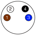 |
1=POWER SUPPLY (Brown) or IEPE + 2=AC or DC SIGNAL (White) 3=GROUND (Blue) or IECE – 4=COMMUNICATION LINE-GAIN SELECTOR – should be left floating if not used (Black) (5)=braided shielded – can be connected to the chassis ground |
Any cable with an M8-4 pins FEMALE<>FREE END shielded connector is suitable for installation. Maximum recommended cable length is 30 m, based on the EMC tests that SDT has successfully passed.
Once the sensor is connected, you need to configure the acquisition system according to the default configuration of the sensor. Please refer to the technical documentation of the sensor as well as your acquisition system to understand the procedure.
The default/factory configurations are listed below:
| CONMONSense | Factory settings | Full range | Optimal range |
| RSV.00X | Gain = +60 dB, AC mode only* | [0-10] V | -/+ 2 V around Vbias = 3 V |
| RSIE.00X | Gain = +60 dB, AC mode only | -/+ 2 V around VIEPE | |
| RSC.00X | Gain = +60 dB, AC mode only* | [0-40] mA | -/+ 8 mA around Ibias = 12 mA |
| RSC.10X | DC mode only | [4-20] mA | 4 mA to 20 mA |
| RSV.11X | DC mode only | 0.28 V to 1.4 V |
All our contact sensors are factory calibrated, which ensures interchangeability and accuracy within their specific resonant band-pass. The various amplification stages are electronically compensated at the output of production.
However, to maintain their accuracy over time, we offer a calibration service to do a full check of the acquisition chain (+ calibration).
Our calibration service is an additional offering that we provide to our customers to ensure that their devices perform at their best. We typically recommend that calibration is performed annually, depending on the sensor type and usage conditions. In some cases, calibration is required by certain regulations.
For permanent installation with CONMONSense, periodic calibration is no longer required or recommended as Industrial DAQ systems are usually not periodically calibrated but still can be done upon demand, like any standard accelerometer.
CONMONSense RSC (4-20 mA Sensor)
One of the major benefits of the 4-20 mA output standard is its high immunity to electrical noise, making it ideal for industrial applications where electrical interference can be a problem. This feature ensures accurate and consistent readings over long distances, even in harsh environments where other types of signals may be prone to interference.
Note that the sensor does need an external 24 VDC supply capable to deliver at least 40 mA.
CONMONSense wiring:

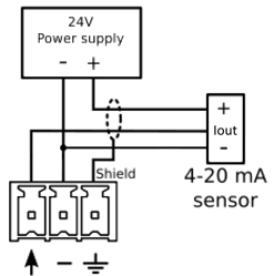
1 = 24 VDC Power supply (+)
2 = Current output (Iout)
3 = 0 V (-)
4 = Communication line (should be left floating if not used)
If your system has a dedicated 4-20 mA input, here is a possible wiring:
If your system does not have a dedicated 4-20 mA but has an analog voltage input, here is a possible wiring:

Note that these wirings are only used as example, you should refer to your system technical document to ensure a correct wiring with your installation.
Static mode:
![]()
Equation for each amplification:
![]()
Example: a static output current of 12 [mA] is the result of a sensor output voltage of (0.012 * 10) = 0.120 [V] or 120 [mV] or 101.5 [dB]µV
![]()
Example: a static output current of 12 [mA] is the result of a sensor output voltage of (0.012 * 2.5) = 0.03 [V] or 30 [mV] or 89.5 [dB]µV
![]()
Example: a static output current of 12 [mA] will result in a sensor output voltage of (0.012 / 1.6) = 0.0075 [V] or 7.5 [mV] or 77.5 [dB]µV
![]()
Example: a static output current of 12 [mA] will result in a sensor output voltage of (0.012 / 6.3) = 0.0019 [V] or 1.9 [mV] or 65.5 [dB]µV
![]()
Example: a static output current of 12 [mA] will result in a sensor output voltage of (0.012 / 25.1) = 0.00048 [V] or 0.48 [mV] or 53.5 [dB]µV
![]()
Example: a static output current of 12 [mA] will result in a sensor output voltage of (0.012 / 100) = 0.00012 [V] or 0.12 [mV] or 41.5 [dB]µV
Dynamic mode:
![]()
Equation for each amplification:
![]()
Example: a dynamic output current of 1 [mA] will result in a sensor output voltage of (0.001 * 208.25) = 0.20825 [V] or 208.25 [mV] or 106.3 [dB]µV
![]()
Example: a dynamic output current of 1 [mA] will result in a sensor output voltage of (0.001 * 52) = 0.052 [V] or 52 [mV] or 94.3 [dB]µV
![]()
Example: a dynamic output current of 1 [mA] will result in a sensor output voltage of (0.001 * 13) = 0.013 [V] or 13 [mV] or 82.3 [dB]µV
![]()
Example: a dynamic output current of 1 [mA] will result in a sensor output voltage of (0.001 * 3.3) = 0.0033 [V] or 3.3 [mV] or 70.3 [dB]µV
![]()
Example: a dynamic output current of 1 [mA] will result in a sensor output voltage of (0.001 / 1.2) = 0.00083 [V] or 0.83 [mV] or 58.3 [dB]µV
![]()
Example: a dynamic output current of 1 [mA] will result in a sensor output voltage of (0.001 / 4.8) = 0.00021 [V] or 0.21 [mV] or 46.3 [dB]µV
Note that the dynamic mode is an alternative output (AC) with a bias current (DC) of 12 [mA].
In order to modify the internal amplification of the sensors or to switch from static to dynamic mode, a communication needs to be established between the system and the sensor.
Using a digital output
If your system has a digital output module you can connect one output to the sensor communication line using this kind of schematic:
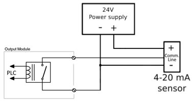
Then simply generate pulses according to the CONMONSense datasheet in order to modify the amplification or the mode.
Using a serial communication
It is also possible to communicate using a serial communication with the following specifications:
- Protocol: UART
- Baudrate: 9600 bps
- Data bits: 8
- Parity: Even
- Stop bit: 1
CONMONSense sensors are using a proprietary protocol described in the datasheet.
The best way to implement an amplification control is by following these simple rules:
Static mode
- If the static output current (DC) is higher than 20 [mA] à decrease the amplification by one step (12 [dB])
- If the static output current (DC) is lower than 4 [mA] à increase the amplification by one step (12 [dB])
Dynamic mode
- If the signal peak is higher than 18 [mA] (or 6 [mA] if bias current is removed) à decrease the amplification by one step (12 [dB])
- If the signal peak is lower than 13 [mA] (or 1 [mA] if bias current is removed) à increase the amplification by one step (12 [dB])
Note that the dynamic mode is an alternative output (AC) with a bias current (DC) of 12 [mA].
CONMONSense RSC (TRUE 4-20 mA Sensor)
CONMONSense RSV (0-10 V Sensor)
Note that the sensor does need an external 24 VDC supply capable to deliver at least 40 mA.
CONMONSense wiring:
1 = 24 VDC Power supply (+)
2 = Voltage output (Vout)
3 = 0 V (-)
4 = Communication line (should be left floating if not used)
If your system has a dedicated 0-10 V analog voltage input, here is a possible wiring:
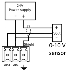
Note that this wiring is only used as an example, you should refer to your system technical document to ensure a correct wiring with your installation.
Static mode:
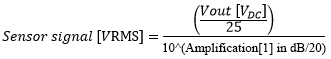

Equation for each amplification:
![]()
Example: an output voltage of 5 [V] will result in a sensor output voltage of (5 / 25) = 0.2 [V] or 200 [mV] or 106 [dB]µV
![]()
Example: an output voltage of 5 [V] will result in a sensor output voltage of (5 / 100) = 0.05 [V] or 50 [mV] or 94 [dB]µV
![]()
Example: an output voltage of 5 [V] will result in a sensor output voltage of (5 / 400) = 0.0125 [V] or 12.5 [mV] or 82 [dB]µV
![]()
Example: an output voltage of 5 [V] will result in a sensor output voltage of (5 / 1575) = 0.0032 [V] or 3.2 [mV] or 70 [dB]µV
![]()
Example: an output voltage of 5 [V] will result in a sensor output voltage of (5 / 6275) = 0.0008 [V] or 0.8 [mV] or 58 [dB]µV
![]()
Example: an output voltage of 5 [V] will result in a sensor output voltage of (5 / 25000) = 0.0002 [V] or 0.2 [mV] or 46 [dB]µV
Dynamic mode:

Equation for each amplification:
![]()
Example: a dynamic output voltage of 1 [V] will result in a sensor output voltage of (1 / 1.2) = 0.833 [V] or 833 [mV] or 118.3 [dB]µV
![]()
Example: a dynamic output voltage of 1 [V] will result in a sensor output voltage of (1 / 4.8) = 0.208 [V] or 208 [mV] or 106.3 [dB]µV
![]()
Example: a dynamic output voltage of 1 [V] will result in a sensor output voltage of (1 / 19.2) = 0.0521 [V] or 52.1 [mV] or 94.3 [dB]µV
![]()
Example: a dynamic output voltage of 1 [V] will result in a sensor output voltage of (1 / 75.6) = 0.0132 [V] or 13.2 [mV] or 82.3 [dB]µV
![]()
Example: an output voltage of 1 [V] will result in a sensor output voltage of (1 / 301.2) = 0.0033 [V] or 3.3 [mV] or 70.3 [dB]µV
![]()
Example: an output voltage of 1 [V] will result in a sensor output voltage of (1 / 1200) = 0.00083 [V] or 0.83 [mV] or 58.3 [dB]µV
Note that the dynamic mode is an alternative output (AC) with a bias voltage (DC) of 3 [V].
In order to modify the internal amplification of the sensors or to switch from static to dynamic mode, a communication needs to be established between the PLC and the sensor.
Using a digital output
If your PLC has a digital output module you can connect one output to the sensor communication line using this kind of schematic:
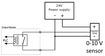
Then simply generate pulses according to the CONMONSense datasheet in order to modify the amplification or the mode.
Using a serial communication
It is also possible to communicate using a serial communication with the following specification:
• Protocol: UART
• Baudrate: 9600 bps
• Data bits: 8
• Parity: Even
• Stop bit: 1
CONMONSense sensors are using a proprietary protocol described in the datasheet.
The best way to implement an amplification control is by following these simple rules:
Static mode
- If the output voltage (DC) is higher than 5 [V] à decrease the amplification by one step (12 [dB])
- If the output voltage (DC) is lower than 1 [V] à increase the amplification by one step (12 [dB])
Dynamic mode
- If the signal peak is higher than 4.5 [V] (or 1.5 [V] if bias voltage is removed) à decrease the amplification by one step (12 [dB])
- If the signal peak is lower than 3.5 [V] (or 0.5 [V] if bias voltage is removed) à increase the amplification by one step (12 [dB])
Note that the dynamic mode is an alternative output (AC) with a bias voltage (DC) of 3 [V].